

How To Repair Cdi Motorcycle
Y'all are using an out of date browser. It may not display this or other websites correctly.
Y'all should upgrade or utilize an culling browser.
Y'all should upgrade or utilize an culling browser.
- #one
My CDI, ignition coil, and stator ringlet all scrap the dust after I failed to tighten up the screws sufficiently on the stator plate upon reassembly. A local technician replaced the SCR and rewound the stator coil, and I bought a generic ignition gyre that has one.5 ohms on the primary. Information technology works only the spark is weaker. Hopefully presently I'll take an original KDX ignition gyre put in. I've heard that due to moisture condensation information technology is common for the stator curl to lose proficient contact with ground (chassis common), so information technology is important to go on those contact places clean. I besides imported a used CDI and ignition gyre (both not working. The coil primary simply had .2 ohms whereas information technology should take 1ohm) from a normal KDX and I took the CDI apart and replaced its SCR and it works now. I will also replace the capacitor once I receive information technology in the mail. I suspect that the capacitor starts to leak after it gets hot.(They do pass spikes of considerable current to the coil). I didn't even know that these CDI's are repairable only at present I encounter that they utilise mutual components and no blazon of "brain" integrated circuit.(it doesn't have any IC'southward). Then from my experience I want all to know that CDI'south tin exist repaired. The repaired CDI from my KDX 200SR (Intl model) was repaired and then sealed with epoxy before I got to await inside. From computing the input resistance (past applying -nine volts across wht/red and black wires and measuring the current and so calculating the resistance. 9 - .6 (voltage beyond diode)=eight.4, 8.4/current=resistance) I found out that the SR CDI uses 27 ohms, whereas a regular KDX CDI uses 16 ohms. If you try to measure the resistance (from the wires earlier tearing into information technology) with an ohmmeter it won't read annihilation if information technology is non applying at to the lowest degree .6 volt, which is needed to turn on the diode. But I really don't recommend this method since the issue depends on the meter used. But testing the CDI's on my bench at 3000rpm (50hz) I saw that the spark timing is simply a tad after on the non-SR CDI (look for the pocket-size voltage change afterwards the betoken goes negative), although maybe the timing curve is different at high revs.
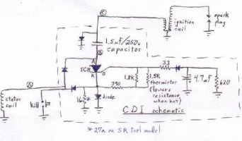
The following drawing is the CDI schematic for a normal KDX (non SR which may have other part values dissimilar other than the input resistor). At http://www.geocities.com/a57ngel/moto/CDI.html are the schematic, parts layout on the circuit lath, lath layout inside the CDI box, simple testing circuit, and voltage waveforms at three places. The parts most probable to fail, in gild of liklihood, are the SCR, ane.5uf capacitor, diodes, and 16 ohm resistor. I would say to always supplant the SCR (Radio Shack sells a skillful 4A/600v SCR which I used with success), and if the ignition coil is reading less than 1 ohm on the chief side then also supervene upon the 1.5uf capacitor (which was allowing as well much current to pass to the coil). Test all the diodes and the 16 ohm resistor and replace as necessary. To get to the parts yous'll need to cut the top and sides off of the plastic container. (aye, essentially butchering it. Yous tin can replpace the box with the i listed below). Be careful because the lesser of the parts board is almost butting up to the top of the container. I have read that soaking the exposed silicone (which encases all the parts and is mixed with white stones) in acetone for three days will dissolve it or at least loosen it up a lot. I oasis't tried that since I tin't find whatsoever acetone hither. You tin can dig out the silicine/stones with a knife but go slowly so as non to harm components (specially the large xanthous capacitor).
Go to http://www.geocities.com/a57ngel/moto/CDI.html for more... :ride:
Attachments
Last edited:
- Thread starter
- #2
I know that most people don't know anything near electronics and are not able to even unsolder a part from the parts lath. In that case just remove the silicone from around the parts, take the CDI to a radio/tv techincian, then enquire him to test all the resistors and diodes. So order from Mouser the SCR , capacitor (i.5uf), and project box and whatsoever parts that the technician found defective. And so when the parts arrive have the technician install them. Then put on a bunch of silicon, install it in the projection box, and screw information technology in place. All done, good as new, and much cheaper than replacing the CDI with a new one!
- #3
Very cool, I've never repaired electronics for bikes but I have made a number of "car" parts dorsum in the day "before married woman" when I played with junkyard cars for fun (and transportation)
- #four
Terminal edited:
- Thread starter
- #5
Similar Topics
- Forums
- Dirt Bike Discussions By Brand
- Canadian Daves JustKDX
- This site uses cookies to help personalise content, tailor your experience and to go on you logged in if yous register.
By continuing to use this site, you lot are consenting to our employ of cookies.

How To Repair Cdi Motorcycle,
Source: https://dirtrider.net/forums3/threads/how-to-repair-a-cdi.98813/
Posted by: smiththerhatim.blogspot.com
0 Response to "How To Repair Cdi Motorcycle"
Post a Comment